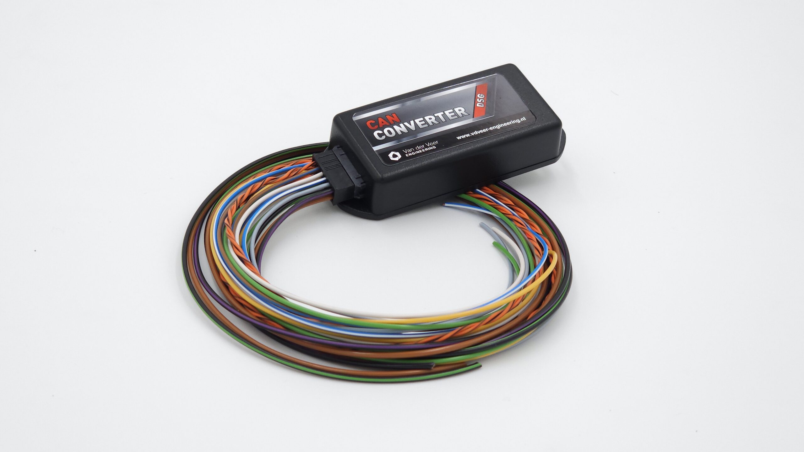
Confirm your gearbox model, TCU, vehicle CAN network and the functions you need. The product supports selected VW PQ and VW MQB setups. Check the exact gearbox and TCU, particularly for MQB DQ500 applications.
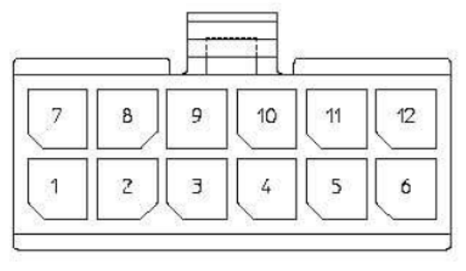
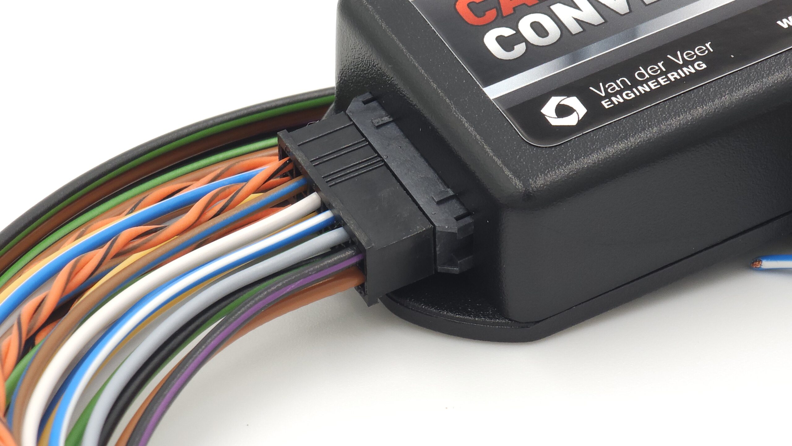
Use the connector orientation in the diagram. Wire colours in the table refer to the convertor loom.
Pin
Wire colour
Function
1
Orange/Black
CAN High
2
Brown/Blue
Starter-block relay control, ground output
3
White
Optional 12 V brake input
4
Blue/White
VSS speed output
5
Grey
LIN bus
6
Black/Purple
Switched 12 V supply
7
Orange/Brown
CAN Low
9
Yellow
Shift Down, ground-switch input
10
Green
Shift Up, ground-switch input
11
Black/Green
12 V reverse-light output
12
Brown
Ground
On current DSG hardware, the analog input is the optional 12 V brake input on pin 3. Pin 4 carries the VSS speed output to a compatible speedometer.
Connect the signals your setup uses
Use the switched 12 V, ground, CAN High and CAN Low connections in the pinout.
For ground-switch paddles, use the documented Shift Up and Shift Down inputs. For LIN paddles, confirm the steering-wheel hardware and required LIN mode before connecting the LIN bus.
If your setup uses the optional analog brake signal, the White wire on pin 3 is the 12 V brake input.
Use the Blue/White wire on pin 4 for a compatible VSS speedometer. The Black/Green wire on pin 11 is the 12 V reverse-light output.
Use the Brown/Blue wire on pin 2 as a ground-switched relay control signal. Keep starter-motor current out of this circuit.
Power up and check the signals
Verify the wiring and connector orientation before applying power.
On Home, check the available signals and communication indicators. Verify the brake, reverse, selector and paddle signals that your installation uses while the vehicle is stationary.
If expected signals are missing, use the diagnostic checklist and send support your gearbox, TCU and firmware details.