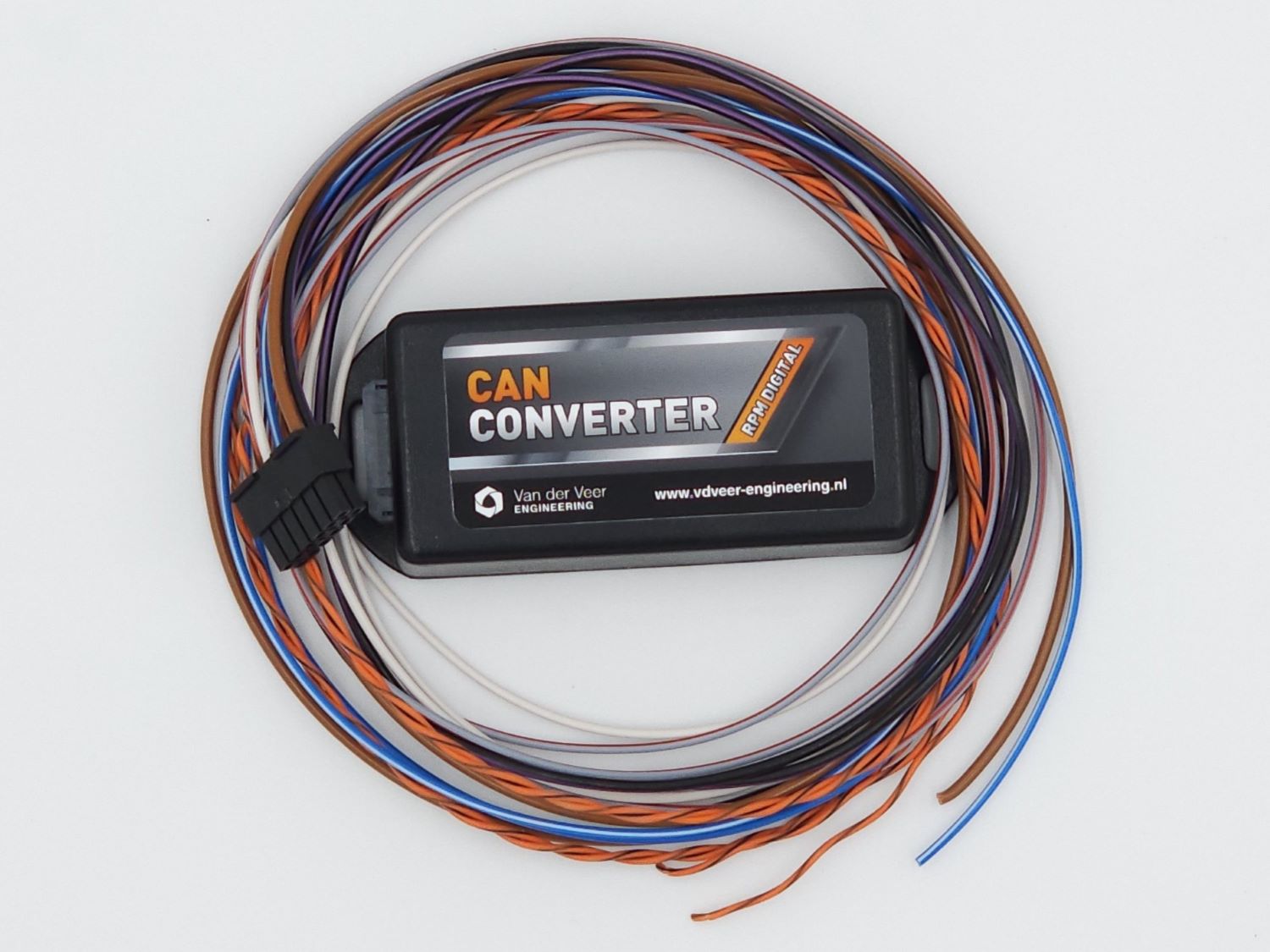
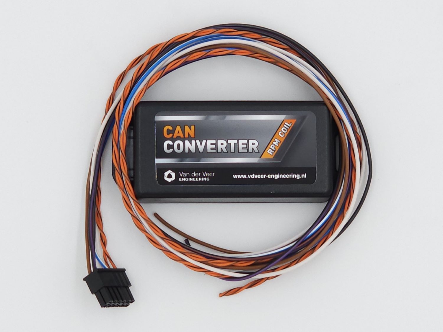
Check the label on your convertor and verify the signal required by your instrument cluster. The documented Coil variant supplies a high-voltage pulse for compatible coil tachometers, such as those in Golf Mk1 and Mk2 examples. The documented Digital variant supplies a 12 V pulse for compatible clusters, such as the Golf Mk3 and Corrado examples.
High-voltage coil output. The Black/Red wire on pin 11 is for a compatible coil tachometer only. Connect and insulate it before applying power. Use your vehicle’s wiring diagram to verify the cluster and fusebox connections.
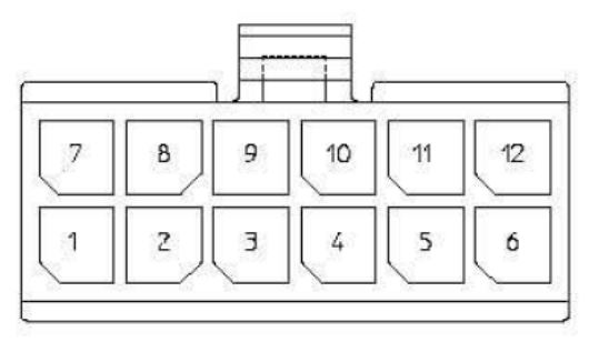
12-pin connector and wiring
Use the pin numbers and the connector orientation shown in the manufacturer’s diagram. This table describes the manual’s pinout. Output availability depends on your unit and configuration.
Pin
Wire colour
Function
1
Orange/Black
CAN bus High input
2
Gray/Red
Output 1 · 12 V RPM pulse for compatible Mk3 and Corrado clusters
3
Blue/White
Output 2 · VSS speed signal in VSS mode
4
Brown/Blue
Output 4 · MIL light, ground-switched output
5
Brown/White
Output 5 · EPC light, ground-switched output
6
Black/Purple
Switched 12 V supply
7
Orange/Brown
CAN bus Low input
8
Yellow
Output 3 · coolant temperature
9
White
VSS speed input
10
Black/White
Input 2 · unused in the manual
11
Black/Red
Output 1 · high-voltage RPM pulse for a compatible coil tachometer
12
Brown
Ground
CE1 and CE2 connection examples
The wire colours below refer to the vehicle side. Confirm the fusebox type and the actual wire at each position using the vehicle’s wiring diagram.
Fusebox
Example
Signal
Position and vehicle wire
CE1
Golf Mk1 / Mk2
RPM
D26 · Red/Black
CE2
Golf Mk2 / Mk3
RPM
G1/12 · white connector · Green/Black or Red/Black
CE2
Golf Mk3
Speed
G1/11 · white connector · White/Blue
CE2
Golf Mk2 / Mk3
Coolant
G2/3 · white connector · Yellow/Red
Power up and verify
Check that the wiring is secure and insulated before applying power.
Choose the CAN protocol for your source ECU and the RPM Output setting for the receiving cluster.
Check engine RPM and the connection indicators on Home. If the convertor receives RPM but the tachometer reads incorrectly, check the cluster’s output type and RPM Output setting.